DC Circuits: Kirchhoff’s Laws and Loaded Sources
A circuit drawing is a claim about connections, not a picture of physical wire positions. Two components are in parallel only if both ends connect to the same two nodes. They are in series only when the same current must pass through both, with no branching junction between them.
Two conservation rules
The junction rule says
It follows from charge conservation when appreciable charge is not accumulating at the node. In a transient, charge accumulation must be accounted for; capacitors explicitly model one important way this happens.
The ordinary loop rule says the signed voltage changes around a closed loop sum to zero. Choose a traversal direction. Crossing an ideal source from its negative to positive terminal contributes +ℰ; moving through a resistor in its assumed current direction contributes -IR. A negative solved current means the chosen direction was opposite reality, not that the method failed.
This is a lumped-circuit model: propagation delays, radiated energy, and unmodeled changing magnetic flux are negligible. If a magnetic flux threads the loop and changes, include the induced emf. Conservation still holds; the simplified inventory was incomplete.
Series and parallel results are consequences
For resistors in series, the voltage drops add while current is common: V=I(R₁+R₂). Hence Req=R₁+R₂.
For parallel resistors the voltage is common and currents add:
Adding another positive-resistance parallel path lowers equivalent resistance. It need not leave every other current unchanged if the source has internal resistance.
Worked network: the source is part of the circuit
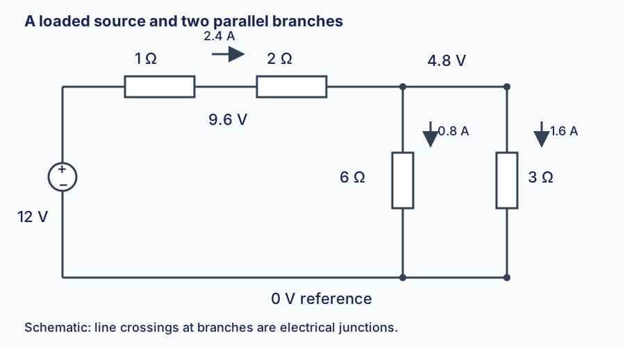
Take a 12 V emf source with 1 Ω internal resistance. Outside it, put 2 Ω in series with parallel branches of 6 Ω and 3 Ω. Their equivalent is 2 Ω, so the full resistance seen by the emf is 1+2+2=5 Ω.
The source current is 2.4 A. Its terminal voltage is only 12-(2.4)(1)=9.6 V. The outer series resistor drops 4.8 V, leaving 4.8 V across both branches. Their currents are 0.8 A and 1.6 A, which sum to 2.4 A.
Check energy independently:
- Source power: 12(2.4)=28.8 W.
- Internal loss: (2.4)²(1)=5.76 W.
- Outer series resistor: (2.4)²(2)=11.52 W.
- Branch losses: (0.8)²(6)=3.84 W and (1.6)²(3)=7.68 W.
The losses total 28.8 W. This check catches sign and topology errors that plausible-looking currents may hide.
Now disconnect the 3 Ω branch. Current becomes 12/(1+2+6)=1.33 A, and the remaining 6 Ω resistor has 8.0 V across it. Its current has increased from 0.8 to 1.33 A, although total source current fell. Removing the competing branch reduced voltage loss upstream.
Networks that do not collapse into series and parallel
Use a reference node and assign unknown node voltages. At each other node, express every outgoing resistor current as (V(node) − V(neighbor))/R, and set their sum to zero, including source currents as appropriate. Alternatively assign independent loop currents and write signed voltage equations. Solve the simultaneous linear equations, then check junctions and total power.
An ideal voltmeter draws no current and reads across two nodes; an ideal ammeter has zero resistance and goes in series. Real instruments perturb the circuit. Putting a low-resistance current meter directly across a source is effectively creating a short, not measuring its ordinary operating current.