Steering Geometry and Tire Forces
Pointing both front wheels through the same angle sounds like steering. In a tight turn it makes the wheels disagree about where the car's turning center is. Steering geometry resolves that low-speed conflict; tire deformation adds a different problem at speed.
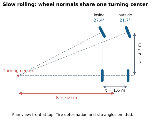
A common center, unequal angles
Imagine ideal rigid wheels rolling slowly without sideways slip. Extend a line sideways from each wheel, perpendicular to its rolling direction. All four lines must meet at the instantaneous center of the turn. With unsteered rear wheels, that center lies along the extended rear axle.
Let wheelbase be L, front track width t, and the rear-axle midpoint's turning radius R. The inside and outside front steer angles satisfy
Subtracting the cotangents gives the ideal Ackermann relation:
The inside wheel steers more sharply because its path bends around a smaller radius. For L=2.7 m, t=1.6 m, and R=6.0 m, the angles are approximately 27.4° inside and 21.7° outside. These hypothetical dimensions generate the diagram; they are not a Mustang chassis reconstruction. MathWorks' steering geometry model.
A rack-and-pinion converts steering-shaft rotation into lateral rack movement, transmitted by tie rods to steering arms. A steering box and linkage accomplish a similar command-to-wheel-angle function with different packaging. The linkage's pivot locations determine how left/right angles relate through travel; a real mechanism generally approximates a chosen steering characteristic rather than meeting ideal Ackermann at every angle. Power assistance reduces driver effort by adding hydraulic or motor torque, but does not supply additional road grip.
At speed, wheels need slip angle to make lateral force
A pneumatic tire is deformable. The angle between the direction the wheel points and the direction its contact region travels is its slip angle. Within a small-angle range, lateral force can be approximated by Fy=Cα, where C is cornering stiffness and the sign convention must be defined consistently. The relation becomes nonlinear and eventually saturates. Slip angle here does not mean the whole tire is necessarily sliding uncontrollably. Michelin describes the deformation mechanism.
Thus ideal Ackermann is a useful low-speed geometric baseline, not a complete high-speed handling prescription. Front and rear tires can require different slip angles, their vertical loads change in a turn, and suspension compliance changes their orientation. A simple bicycle model replaces each axle's tires with one equivalent tire and relates curvature, steering, and those slip angles. It explains why an actual car can need more steering than pure geometry predicts as lateral acceleration rises.
In a simple steady-state description, understeer means steering demand increases with speed/lateral acceleration beyond the geometric baseline for a fixed turn radius; oversteer is the opposite trend. Neither label means that an axle always loses all grip. The distinction is a response property within specified operating conditions, and near the limits the linear model is inadequate. MathWorks illustrates how cornering stiffness changes steering demand.
Alignment terms describe different planes
- Toe is the relative inward/outward pointing of the wheels seen from above. It affects straight-line scrub and how the tires respond to steering.
- Camber is wheel tilt from vertical seen from the front or rear. Suspension roll and travel change camber and therefore tire contact behavior.
- Caster is fore-aft tilt of the steering axis seen from the side. Together with steering-axis geometry and tire forces it contributes to steering feel and self-centering.
- Trail and scrub radius locate the steering-axis ground intersection relative to the tire contact patch. They determine moment arms through which tire forces act on steering.
These are relationships, not independent “more is better” settings. A bump can change toe even with the steering wheel held fixed because suspension and tie-rod arcs differ: bump steer. This is why steering and suspension must be understood together.
A shared force budget
A tire supplying lateral force cannot simultaneously use unlimited longitudinal force for braking or acceleration. A friction circle or ellipse is a useful approximate envelope, not a universal tire law. Steering requests a path; the available forces determine whether the car can follow it.